 serin labs
Wiring Reference: CN105 to Grove
Pinout and wiring reference for connecting an M5Stack Atom S3 Lite or NanoC6 to a Mitsubishi heat pump CN105 port.
Shortcut: Buy a Ready-Made Cable
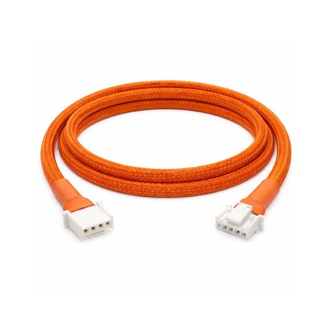
This page is a reference for building the cable yourself. Prefer not to? Buy a ready-made CN105-to-Grove cable — no crimping or soldering required — or get the complete Serin Controller with the cable included.
Wiring Diagram
Cable Options
Detailed Pinout Reference
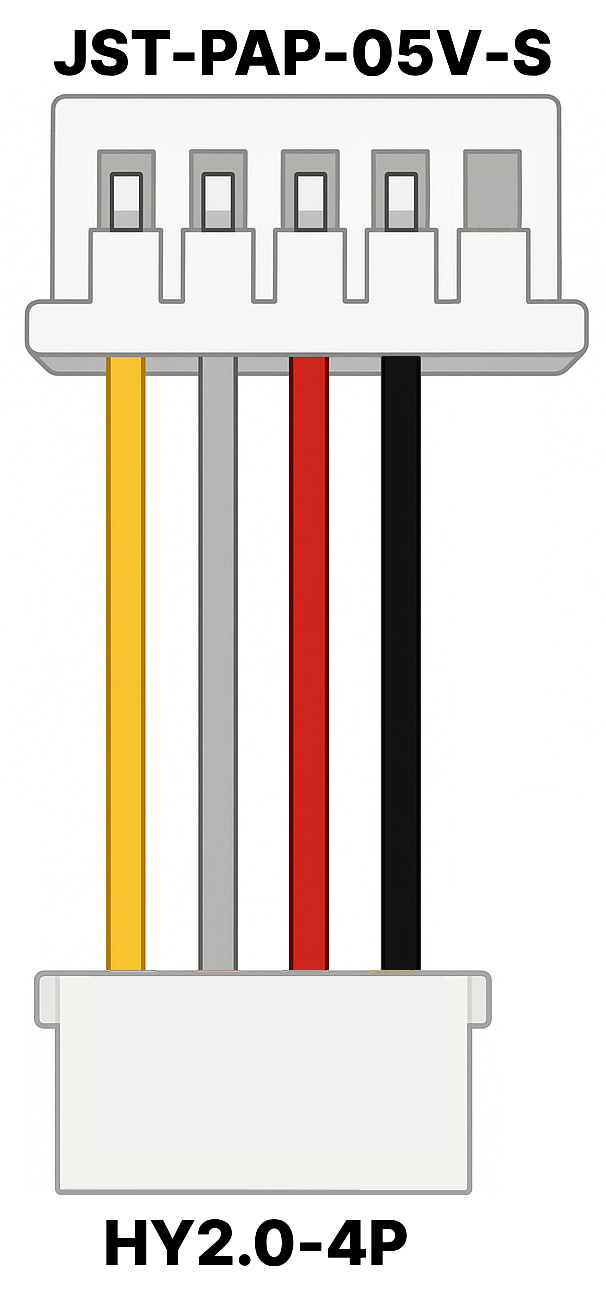
CN105 (JST-PAP-05V-S) Pinout
| Pin | Signal | Description |
|---|---|---|
| 1 | 12V | Not used |
| 2 | GND | Ground |
| 3 | 5V | 5V Power |
| 4 | TX | Data output from HVAC (5V logic) |
| 5 | RX | Data input to HVAC (5V logic) |
Grove (HY2.0-4P) Pinout for M5Stack Atom S3 Lite and NanoC6
| Pin | Signal | Description |
|---|---|---|
| 1 | G | Ground (connects to ESP32 GND) |
| 2 | 5V | 5V Power (connects to ESP32 5V/VCC) |
| 3 | G2 | RX (connects to ESP32 UART RX pin) |
| 4 | G1 | TX (connects to ESP32 UART TX pin) |
References
Disclaimer
Always turn off power to your HVAC unit before connecting or disconnecting any cables. This reference is provided as-is. Wiring is at your own risk.